Effect of thickness and elastic modulus of base layer on stress distribution around Class I composite restorations: A finite element study
현재 샌드위치법은 탄성계수가 낮은 재료를 탄성계수가 높은 복합 레진 하방에 베이스층으로 형성하게 되는데, 아직 임상적으로 표준화된 방법이 정해져 있지 않다. 따라서 본 연구는 복합 레진 하방에 베이스층을 형성하였을 때 그 두께와 재료의 탄성계수가 1급 와동 주위의 응력 분산에 미치는 영향에 대하여 유한요소분석법을 이용하여 연구하였다. 레진강화형 글라스 아이오노머 시멘트인 Fuji II LC와 유동성 레진인 Heliomolar Flow을 베이스 재료, Tetric Ceram HB와 Tetric Ceram을 그 위층에 충전하는 복합레진으로 선정하였다. 하악 제1대구치 모델에 0.0, 0.5, 1.0, 1.5, and 2.0 mm 두께로 베이스 재료를 (가상) 적용한 후 복합레진을 (가상) 충전하였다. NISA II/DISPLAY III 소프트웨어로 유한요소분석을 수행하였다. 와동벽을 따라 형성되는 von Mises stress는 베이스 재료의 적용과 탄성계수에 영향을 받지 않았다. 수직으로 또는 비스듬하게 적용된 하중 하에서 재료와 와동벽 사이의 von Mises stress는 계면접착강도 이하로 나타났다. 결론적으로 베이스 적용의 유무, 두께 혹은 사용된 베이스 재료의 탄성계수는 1급 와동의 응력 분산에 큰 영향을 미치지 않았다.
Keywords:
Resin composite, Base, Stress distribution, Thickness, Elastic modulusINTRODUCTION
A sandwich technique, i.e. placement of lining- or base materials on the cavity floor under composite resin restorations, is widely used in clinical dentistry. In the original sandwich technique, glass ionomer (GI) cement was used to cover the cavity floor. Later, resin-modified glass ionomer (RMGI) (Croll, 2004) and more recently flowable composites, preferred because of their superior handling properties (Fortin & Vargas, 2000; Christensen, 2003), were used too. The primary purpose of these bottom layer materials was to protect pulp and prevent formation of a bacterial, fluid-filled gap nearest the cavity floor or walls (Brannstrom et al., 1991). A belief that the relative soft base layer can absorb the stresses induced from occlusal forces as well as polymerization shrinkage (Kwon et al. 2010) has been another driving force. Some researchers believe that the use of base layer is intrinsic to the success of posterior composite restorations (Croll & Cavanaugh, 2002; Croll, 2004).
Stress absorbing function of base layer, however, has been questioned. For example, Opdam et al. (2007) reported relatively poor clinical result of a closedsandwich restoration, manifested by a fracture of the composites restoration. Oliveira et al. (2008) reported that the use of liner or base material under composite - resin restoration was unlikely to reduce stresses produced by polymerization shrinkage or occlusal loading.
As stress management is a key to the long term integrity of composite resin restoration, effect of the base layer on the stresses especially at the restorative- tooth interface needs special attention. The way how occlusal load transfer across tooth and restoration materials, depending on the structural configuration properties of base layer, needs careful analysis. However, influence of the structural configuration of base layer on stresses has not been well studied although various GI, RMGI cements or flowable composites are being used to form base layers. Accordingly, in the present study we investigated the effect of elastic modulus and thickness, two basic elements that decide structural configuration of base layer, on the stresses around class I cavity restoration using finite element simulation. The null hypothesis was tested that the thickness of the base under a composite restoration would not significantly influence the quality of the restoration in the context of stress distribution.
MATERIALS AND METHODS
We selected Fuji II LC (fl, GC Corp., Tokyo, Japan) and Heliomolar Flow (hf, Ivoclar Vivadent, Schaan, Liechtenstein) as the base layer material, and Tetric Ceram HB (HB, Ivoclar Vivadent) and Tetric Ceram (TC, Ivoclar Vivadent) as the overlying restorative composites, considering their elastic moduli (Table 1).
Mandibular right first molar (#46) was selected for this study, with all the important anatomical data including the height and width of the crown referenced from its mesial aspect presented in a standard textbook.(Ash, 1984) A cavity of 40 mm both in breadth and depth was created with its midline passing the central fossa. A basic assumption was that the coronal part of tooth structure was intact except cavity. Pulp chamber was not included in the analysis model.
Cavity was restored with one of two base materials in various thicknesses (0.0, 0.5, 1.0, 1.5, and 2.0 mm) and then one of two restorative composites. The whole restoration height was maintained at 4 mm by compensating the thickness of composite resin layer according to the base layer. The simulation model codes were expressed using the combination of the material code and the thickness of the base layer. For example, HB/FL0.5 represents that the cavity was filled with 0.5 mm thick Fuji II LC and then with Tetric Ceram HB with a thickness of 3.5 mm.
The restored tooth was modeled using a twodimensional plain strain formulation which suits well with the mesiodistally larger dimension compared to buccolingual direction, both the tooth itself and cavity alike. All the analyses were performed based on a linear elastic assumption using the NISA II/DISPLAY III program provided by EMRC (Troy, MI, USA). An eight node quadratic element was used to build the mesh model. It was assumed that all the materials were appropriately applied and resultantly perfect bonding interfaces were made between the base layer and tooth or restorative composite (Alomari et al., 2001; Ruiz & Mitra, 2006)
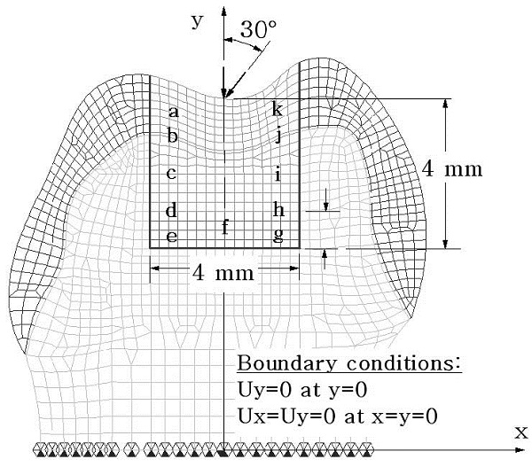
Two load conditions simulated were a vertical and a buccally-inclined load of 100 N. The buccal inclination angle was 30 degrees relative to the tooth axis. Forces were applied at the central fossa. All the nodes on the bottom surface of the crown were fixed as geometrical boundary condition.
A typical finite element model employed in this study is shown in Figure 1. The von Mises stress was selected to investigate the stresses along the interface between tooth and restoration materials. For this 11 reference points at the nearest nodes to the cavity walls or floor within the restoration were specified, as presented in Figure 1.

Two-dimensional finite element mesh model showing the cavity, loading directions, and the eleven reference points where von Mises stresses were monitored. The thickness of base materials were 0.0, 0.5, 1.0, 1.5 or 2.0 mm. Ux and Uy indicate the displacements in the direction of x and y axes, respectively.
RESULTS
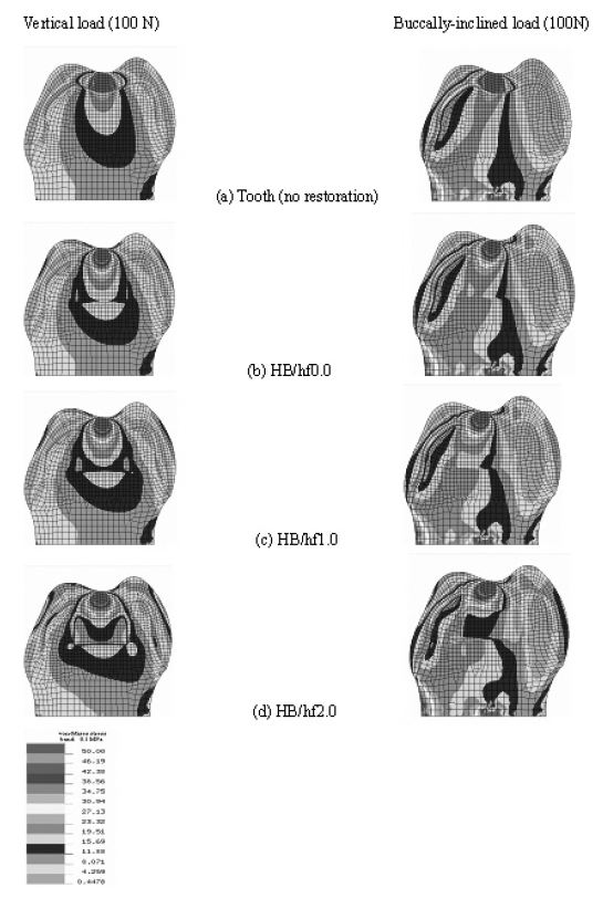
Stress distribution around the restoration was observed via stress band plot first. Figure 2 presents representative von Mises stress distribution recorded in HB/HF models of three different base layer thicknesses together with the case of intact tooth (no restoration). For all simulations, an acute stress concentration, being an artifact due to the application of the load to a single node, was noted (red) at the occlusal top. This stress concentration, did not affect the stresses at the restorative-tooth interface significantly. Except here the stresses exhibited quite a smooth and continuous distribution pattern in over all. At the right and left corners where the cavity wall and cavity floor met at a right angle, no abrupt changes in the stress field was observed, revealing that the analysis results were reliable.
Stress pattern in the intact tooth was similar to that in HB/hf0.0 models in overall except that in the former highest stresses developed only within enamel layer. Stresses in HB/hf0.5 and HB/hf1.5 models were in-between of those obtained for HB/hf0.0 and HB/ hf1.0, and HB/hf1.0 and HB/hf2.0, respectively (data not shown). Meanwhile, stress patterns recorded in models of other three groups, i.e. HB/fl, TC/fl and TC/hf models were similar to each of the corresponding HB/hf model which had the same base layer thickness. As also shown in Figure 2, stress distribution was dependent primarily on the loading direction: the higher stresses developed along the direction of the load. Although some distortion in the stress pattern was observed around the base layer, stresses in the restorative composite and tooth tissues appeared to be minimally interrupted by the presence of base layer or by its thickness. Stresses developed below the cavity floor, i.e. beneath the base layer, were virtually the same: light green under vertical loading, and dark green under inclined loading.

The von Mises stress distribution across the tooth and the restoration under a load of 100 N acting in three different directions when the cavity was restored using a HB/hf combination: (a) Tooth (no restoration); (b) HB/hf0.0; (c) HB/hf1.0; and (d) HB/hf2.0 models.
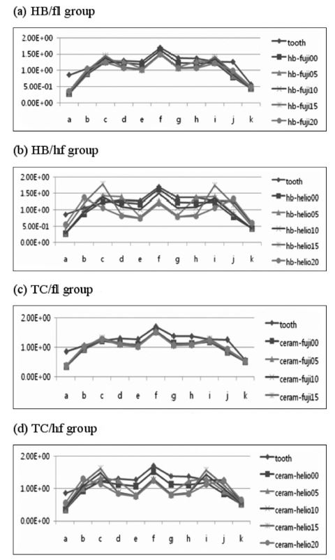
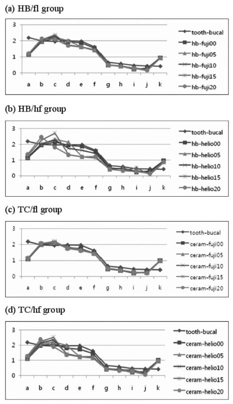
The effect of base layer on the restorative-tooth interfacial stresses was compared in a quantitative manner from stress data recorded at the 11 reference points (Figures 3 and 4). Stress pattern was dependent on the load direction. While the stresses were almost bucco-lingually symmetric when tooth was subject to vertical loading (Figure 3), a significant asymmetry was observed in the case of inclined loading condition (Figure 4). On the other hand, differences in the stress pattern between analysis groups were less significant, for both the load conditions. Either for vertical or for inclined load cases, the interfacial stresses were more affected by the elastic modulus of base layer than that of composite resin. The differences in the stress patterns are more clear when comparing a and b (or c and d) than when a and c (or b and d) are compared.

Von-Mises stresses recorded at the reference points of the cavity under vertical load of 100 N: (a) HB/fl; (b) HB/hf; (c) TC/fl; and (d) TC/hf models.

Von-Mises stresses recorded at the reference points of the cavity under bucally- inclined load of 100 N: (a) HB/fl; (b) HB/hf; (c) TC/fl; and (d) TC/hf models.
The effect of using thicker base layer was witnessed by the lower stresses on the cavity floor. As shown in b’s and d’s, stresses at point e, f, and g were lower by approximately 0.5 MPa. It should be noted that the lower stresses at the cavity floor did not necessarily lead to higher stresses at the cavity wall. Despite the variations in the stress patterns, the influence of base layer on the stress at the restorative-tooth interface, the effect of elastic modulus and thickness combined, was in the order of 1 MPa at maximum (at point e in Figure 4 (b) and (d)).
DISCUSSION
The present study was designed to investigate the effect of elastic modulus and thickness of base layer on the mechanical quality of composite resin based cavity restorations. Two base materials - relatively stiff Fuji II LC and relative flexible Heliomolar Flow and two composite resin systems - relatively stiff Tetric Ceram HB and relative flexible Tetric Ceram were selected. In this study, primary consideration was given to the stresses developing around the cavity restoration depending on the differences in the base layer construction.
Theoretically, the thicker and the more flexible base layer is the lesser loads it will take up resulting in higher stresses in the composite resin restoration, so that the interfacial stresses between tooth and composite resin will increase accordingly. On the other hand, a stiff or rigid base layer will take up a larger portion of occlusal force, and hence result in higher stress state in the base layer which may have a negative impact on its own structural integrity.
Excessive stresses at the tooth/restoration interface can develop such complications as marginal breakdown, microleakage, staining, postoperative sensitivity, secondary caries, and pulpal irritation (ref). Polymerization shrinkage, thermal stimuli, and occlusal loads have been described responsible for the interfacial stress development. For large cavities, especially in posterior teeth, it has been suggested to apply “soft” base materials between the cavity floor and composite resin, which will serve as stress-absorbing element. Due to their higher strain capacity, soft base materials can help reduce the stresses generated from polymerization shrinkage of composite resin. However, the use of soft base layer may need a cost benefit analysis as the soft and flexible base layer can affect on the way occlusal loads transfer between tooth and restoration materials, and eventually on the stresses at the restorative-tooth interface.
The load acting on the occlusal surface of composite will eventually transfer to the dentin via the restorative material. How the load transfer takes place decides the local stress distribution in the tooth tissues and the restorative materials. Basically, occlusal load will be transferred in two directions: horizontally to the cavity wall via the composite layer and/or vertically to the cavity floor via composite and base material. The amount of loads delivered through each of these two directions would be decided by the structural rigidity of the constituent materials (Morgan & James, 1995), which is defined as the product of the elastic modulus (E) and geometric properties (i.e. area (A) or moment of inertia (I)) of each layer. Based on the engineering theory that a more rigid structure takes up more load, and since the use of base material will reduce the structural rigidity of the restoration in vertical direction, the use of a base material was initially expected to allow more loads to transfer horizontally to the cavity wall through the composite and result in higher stresses there. However, stress distributions shown in Figure 2, 3, and 4 revealed that the presence of a base material as thick as up to 2 mm, virtually did not affect the load path.
The direction of occlusal played a more important role in the stress distribution pattern than the base layer itself.. When the load was applied in vertical direction, virtually all the load was transferred to the cavity floor (Figure 2). On the other hand, when the load was acting obliquely, the load transferred mainly to the cavity wall rather than the cavity floor, unaffected by the base materials’ structural configurations.
Stress results on the cavity wall were consistently lower on the enamel wall than on the dentin wall. This may indicate that the dentin/composite bond strength is more important than that between enamel and composite. The level of composite/dentin interfacial stresses was in the range of 0.5 to 3.5 MPa depending on the loading condition, which is lower by a factor of 5 to 10 than the reported composite/dentin interfacial bond strength. This indicates that the strength of composite resin restoration in normal situation would be strong enough even when the forces of higher than 100 N are applied. The present study model used a force of 100 N, yet since the analysis was performed on linear elastic basis, stresses at different force levels can easily be scaled proportionately.
As shown in Figures. 3 and 4, the differences in the interfacial stress data obtained from models with base layer of various thickness was 1.0 MPa at best. This finding indicates that the effect of elastic properties of composite resin and base material, and of their thickness played only a limited role in the distribution of interfacial stresses. It also suggests that the mechanical strength of composite restoration may not be affected by differences in the base layer design. In other words, a thick use of base materials, i.e. up to 2 mm for a cavity of 4 mm in depth, will not deteriorate the static mechanical strength of the restoration. Furthermore, since softer materials lying beneath a hard material may provide cushioning effect when a load is applied in a dynamical manner, a rather thicker base material may be even advantageous, as can be seen with the case of enamel/dentin combination in real teeth.
From a sheer static perspective, the use of thick base material did not have an adverse effect on the quality of composite restoration. However, since the effect of polymerization shrinkage or stresses thereof was not taken into account in this study a definite conclusion should be reserved. Previous studies of Cadenaro et al. (2009) revealed that the use of flowable composites does not guarantee for reduction in polymerization shrinkage stress. Braga et al. (2003) tested several flowable composites and reported that the elastic modulus for some flowable composites might not be low enough to provide significant stress relief. Therefore, a well designed further study to address this matter more comprehensively is still needed. It should be noted that flowable composites base layer may not fulfill the traditional purpose of liners: pulp protection (Christensen, 2003).
CONCLUSIONS
Within the limitations of the present model study, the von Mises stresses along the cavity wall and floor were virtually not affected by the presence, elastic modulus and thickness of base material. The null hypothesis was therefore retained. More importantly, as the von Mises stresses between the restored material and the cavity wall, both under vertically and obliquely acting loads, were well below the interfacial bond strength, although slightly higher stresses were recorded under obliquely acting load, it is unlikely that the differences in the elastic properties of both the overlying composites and base layer had significant effect on the von Mises stress distribution along the cavity wall and floor.
Acknowledgments
This research was supported by Kyungpook National University Research Fund, 2013.
References
- QD Alomari, JW Reinhardt, DB Boyer, Effect of liners on cusp deflection and gap formation in composite restorations, Oper Dent, (2001), 26, p406-411.
- MM Ash, Wheeler’s Dental Anatomy, Physiology and Occlusion, 6th ed. Philadelphia, PA, USA: W.B. Saunders Company, (1984).
-
RR Braga, TJ Hilton, JL Ferracane, Contraction stress of flowable composite materials and their efficacy as stress-relieving layers, J Am Dent Assoc, (2003), 134, p721-728.
[https://doi.org/10.14219/jada.archive.2003.0258]

-
M Brannstrom, B Mattsson, B Torstenson, Materials techniques for lining composite resin restorations: a critical approach, J Dent, (1991), 19, p71-79.
[https://doi.org/10.1016/0300-5712(91)90093-E]

-
M Cadenaro, G Marchesi, F Antoniolli, C Davidson, E De Stefano Dorigo, L Breschi, Flowability of composites is no guarantee for contraction stress reduction, Dent Mater, (2009), 25, p649-654.
[https://doi.org/10.1016/j.dental.2008.11.010]

- GJ Christensen, Direct restorative materials, What goes where? J Am Dent Assoc, (2003), 134, p1395-1397.
-
TP Croll, RR Cavanaugh, Posterior resin-based composite restorations: a second opinion, J Esthet Restor Dent, (2002), 14, p210-212.
[https://doi.org/10.1111/j.1708-8240.2002.tb00526.x]

-
TP Croll, The "sandwich" technique, J Esthet Restor Dent, (2004), 16, p210-212.
[https://doi.org/10.1111/j.1708-8240.2004.tb00037.x]

-
JW Farah, RG Craig, KA Meroueh, Finite element analysis of a mandibular model, J Oral Rehabil, (1988), 15, p615-624.
[https://doi.org/10.1111/j.1365-2842.1988.tb00199.x]

-
D Fortin, MA Vargas, The spectrum of composites: new techniques and materials, J Am Dent Assoc 131 Suppl, (2000), p26S-30S.
[https://doi.org/10.14219/jada.archive.2000.0399]

- TR Katona, MM Winkler, Stress analysis of a bulk-filled Class V light-cured composite restoration, J Dent Res, (1994), 73, p1470-1477.
-
OH Kwon, DH Kim, SH Park, The influence of elastic modulus of base material on the marginal adaptation of direct composite restoration, Oper Dent, (2010), 35, p441-447.
[https://doi.org/10.2341/09-372-L]

-
MJ Morgan, DF James, Force and moment distributions among osseointegrated dental implants, J Biomech, (1995), 28, p1103-1109.
[https://doi.org/10.1016/0021-9290(94)00139-U]

- L Oliveira, S Duarte Jr, C Araujo, A Abrahao, Polymerization Shrinkage Stress in Composite- resin Restorations Associated Liner/base, IADR 1817, (2008).
- NJ Opdam, EM Bronkhorst, JM Roeters, BA Loomans, Longevity and reasons for failure of sandwich and total-etch posterior composite resin restorations, J Adhes Dent, (2007), 9, p469-475.
- JL Ruiz, S Mitra, Using cavity liners with direct posterior composite restorations, Compend Contin Educ Dent, (2006), 27, p347-351, quiz 352.
