다양한 디지털 스캔 방법에 따른 지르코니아관의 변연 및 내면 간극 비교
초록
본 연구는 CAD/CAM 시스템의 디지털 영상 획득 과정에서 다양한 방법을 통해 제작한 지르코니아관의 변연과 내면의 간극 크기를 비교 분석하고자 하였다. 좌측 하악 제1대구치 레진 모형에 지대치를 형성하고, 모형 스캔(MS군), 인상체 스캔(IS군), 구내 스캔(OS군)과 치과용 CT 스캔(CT군)을 이용하여 각 군당 각각 15번의 영상을 획득한 후, 각각 15개의 지르코니아관을 제작하였다. 변연과 내면 간극 크기(치경부, 축면, 교합면)를 측정하기 위해 실리콘 레플리카 술식을 이용하였다. 지르코니아관 내부를 저점도의 실리콘 인상재(Examixfine injection type, GC America Inc., USA)로 채우고 지대치에 위치시킨 후, 만능재료시험기(Instron 3345; Instron, Canton, MA, USA)를 이용하여 50 N의 힘으로 5분간 유지시키고 지르코니아관을 분리하였다. 디지털 현미경(JTZ-7XT, Samwon, Korea)을 이용하여 16개 지점에서 실리콘 두께를 수직으로 측정하고, one-way ANOVA와 Duncan's multiple range test (α=0.05)로 분석하였다. 실험 결과, 변연 간극은 OS군과 MS군이 낮은 간격을 보여 IS군, CT군과 유의한 차이를 보였다(p<0.05). 치경부 간격의 평균값을 비교한 결과, OS군이 가장 낮게 나타나 다른 군과 통계적으로 유의한 차이가 있었고(p<0.05), CT군과 MS군은 서로 유의한 차이가 나타나지 않았다(p>0.05). 축면부 간격의 평균값을 비교한 결과, IS군이 가장 낮게 나타났고, MS군이 가장 크게 나타나 통계적으로 유의한 차이가 있었다(p<0.05). OS군 과 CT군은 서로 유의한 차이를 보이지 않았다(p>0.05). 교합면 간격의 평균값을 비교한 결과, OS군이 가장 낮게 나타났고, CT군이 가장 크게 나타나 유의한 차이가 있었다(p<0.05). MS군은 OS군, IS군과 통계적으로 유의한 차이를 나타내지 않았다. 결론적으로 지르코니아관의 변연 간극과 치경부와 교합면 간극은 OS군이 가장 작았으며, 축면 간극은 IS군이 작았다. 치과용 CT 스캔군을 제외한 모든 군에서 임상적으로 허용할 만한 범위 내에 있었다.
Abstract
In this study, marginal and internal discrepancies of zirconia crowns fabricated with the CAD/CAM (computer aided design – computer aided manufacturing) system were compared. Digital impressions were obtained using model scan (MS), impression scan (IS), oral scan (OS) and dental CT scan (CT). The left mandibular first molar resin tooth was prepared as occlusal 2 mm, axial 1 mm reduction with convergence angle of 6 degree and shoulder margin. After fifteen scan procedures per group, each fifteen zirconia crowns were fabricated. The marginal and internal discrepancies of the crowns were measured using a silicone replica technique with a light body silicone impression material. The replica specimens were sectioned buccolingually and mesiodistally and then examined using a microscope ×160 magnification. The data were statistically analyzed with one-way ANOVA and post-hoc was Duncan’s multiple test (α=0.05). Mean marginal discrepancies of zirconia crowns were significantly lower in OS group and MS group than in IS group and CT group. Mean cervical discrepancies were a statistically significant difference (p<0.05) in the OS group compared to the other groups (p<0.05). The CT group and the MS group did not show any significant difference (p>0.05). The IS group showed the lowest axial discrepancies and the MS group showed the greatest statistically significant difference (p<0.05). There was no significant difference between the OS group and the CT group (p>0.05). The occlusal discrepancies were the lowest in OS group and the largest in CT group, indicating a significant difference (p<0.05). The MS group showed no statistically significant difference from the OS group and the IS group. The marginal discrepancies and cervical discrepancies of the zirconia crowns were lowest in the OS group and the axial discrepancies were lowest in the IS group. All groups except the CT group were within the clinically acceptable range.
Keywords:
Dental CT, Internal discrepancies, Marginal discrepancies, Model scanner, Oral scanner, Zirconia crown키워드:
구강 스캐너, 내면 간극, 모델 스캐너, 변연 간극, 지르코니아관, 치과용 CT서 론
치과 보철 치료에 있어서 치과 수복물의 강도와 심미성의 확보는 임상적으로 중요한 문제이다. 환자의 심미적인 관심이 높아짐에 따라 전치부 수복 치료에서 금속이 치은을 통해 투과되어 보이는 기존의 금속 도재 보철물보다 심미성이 우수한 올세라믹 수복물에 대한 수요가 증가하고 있다. 올세라믹 수복물 중, 지르코니아는 심미성이 높고 생체친화성이 우수하여 전치부에서의 치과 수복재로 성공적으로 사용되고 있다(1,2). 최근에는 강도의 증가로 전치부 뿐만 아니라 구치부 수복에 있어서도 성공적으로 이용되고 있다(3). 지르코니아는 강도가 높기 때문에 기존의 전부도재관 제작 방법을 적용하기에는 한계가 있어 CAD/CAM (computer aided design–computer aided manufacturing) 시스템을 이용하여 절삭 가공을 시행한다. 디지털 영상을 획득하는 과정은 CAD/CAM 시스템을 사용하는데 기초가 되는 중요한 과정이기 때문에 더욱 정밀한 디지털 영상을 얻기 위해 지속적으로 기술 개발과 발전이 이루어지고 있다. 현재 사용되고 있는 디지털 영상 획득 방법에는 석고 모형 스캔, 인상체 스캔, 구내 스캔이 있으며(4-6), 최근 치과용 CT(computer tomography)가 임플란트 진료의 보편화에 따라 광범위하게 보급되면서 CT 스캔을 통한 디지털 모형의 제작 방식도 여러 연구에서 시도되어 왔다(7). 고해상도의 치과용 CT를 이용한 디지털 모형 제작은 고가의 모델스캐너나 구강내 스캐너의 추가적인 구입이 필요 없어 경제성이 높고, 레이저 스캔 디지털 모형과 같은 표면 스캔 방식이 아니라 볼륨 스캔 방식으로 획득되기 때문에 조사 각도나 피사체의 형태에 영향받지 않아 빠른 시간 내에 모형을 획득할 수 있다(8). 최근에는 악교정수술 영역에서 활발히 시도되어 임상적으로 사용되고 있으며(9), 교정 영역에서도 CT 영상을 통한 치열공간분석이 교정치료에 활용하기에 문제가 없음이 보고되었다(10). 그러나 구강 내에 금속 수복물이 존재하는 환자는 CT 촬영 시 노이즈로 인해 정상적인 영상을 얻기 어렵고, 모형제작을 위한 불필요한 방사선 노출이 야기 된다는 단점이 있다. 또한, 아직까지 보철물 제작에 활용 가능한 영상 구성방법이 보고된 바는 없다(11). 임상적으로 디지털 인상 술식을 적용할 때에는 데이터가 실제 지대치의 형태를 얼마나 정확하게 전달하는가와 장비의 반복정확성, CAD/CAM 제작과정을 통하여 완성된 수복물의 적합도 등을 고려해야 할 것이다. 수복물의 부정확한 변연 적합성은 치태침착을 증가시켜 지대치에 이차 치아 우식증과 치주질환을 일으키며(12, 13), 수복물 내면의 시멘트 용해와 미세누출을 증가시켜 이차 치아 우식증과 변연 변색을 일으킬 수 있다(14). 따라서, 변연 간극과 내면 간극은 수복물의 장기적 예후에 매우 중요한 요소이다. 이에 본 연구는 하악 좌측 제1대구치 모형에서 지대치 형성 후, 작업 모형 스캔, 인상체 스캔, 구내 스캔과 치과용 CT 스캔을 이용하여 영상을 획득한 후, 지르코니아관을 제작하여 변연 간극와 내면 간극을 비교 분석하여 정확도 및 임상적 효용성을 알아보고자 한다. 이를 위해 실리콘 레플리카 술식으로 지르코니아관의 변연 간극 및 내면 간극을 비교 평가하였다.
재료 및 방법
1. 주모형 제작
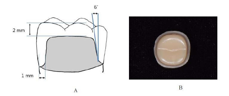
하악 좌측 제1대구치의 dentiform resin tooth (Nissin dental model, Kyoto, Japan)를 삭제하여 지대치 모형을 제작하였다. 지대치 모형은 교합면 2 mm, 축면 1 mm 로 삭제를 시행하였고, 변연은 숄더 변연을 부여하였다. 축면은 밀링머신(S3-Master Milling Unit, Schick Dental, Germany)을 사용하여 6°의 경사를 갖도록 삭제하였다(Figure 1).
2. 디지털 영상 획득과 지르코니아관 제작
완성된 지대치를 모형 스캔(MS), 인상체 스캔(IS), 구내스캔(OS), 치과용 CT 스캔(CT)의 4군으로 나누어 디지털 영상을 획득하였다. 1개의 스캔 파일에 1개의 지르코니아관을 각각 제작하였으며, 이 과정을 각 군당 15번씩 시행하여 총 15개의 지르코니아관을 제작하였다(Table. 1).
- ① 모형 스캔(MS군): 실리콘 인상재(Honigum light body, Hamburg, Germany)를 사용하여 주모형의 인상을 15회 채득한 후, IV형 초경석고(Snow Rock, DK Mungyo Corporation, Korea)를 사용하여 총 15개의 석고 모형을 제작하였다. 완성된 석고 모형은 모델스캐너(Ceramill Map400, Amann Girrbach, Germany)를 이용하여 스캔하였다.
- ② 인상체 스캔(IS군): 실리콘 인상재(Honigum light body, Hamburg, Germany)를 사용하여 주모형의 인상을 15회 채득한 후, 모델 스캐너(Ceramill Map400, Amann Girrbach, Germany)로 각각의 인상체를 스캔 하였다.
- ③ 구내 스캔(OS군): 구강 스캐너(Carestream CS3600, Carestream Health, Atlanta, USA)로 주모형을 직접 15회 스캔하였다.
- ④ 치과용 CT 스캔(CT군): 주모형을 전용 rest 위에 고정한 후, 치과용 CT (Alphard VEGA, Asahi, Japan) 촬영 장치를 이용하여 15회 촬영하였다. 촬영조건은 80 Kvp, 9 mA, scan time은 17초, voxel size 100 ㎛으로 하여 512개의 단면을 촬영하였다. CT에서 얻어진 데이터는 STL (stereolithography) 파일로 변환하였다.
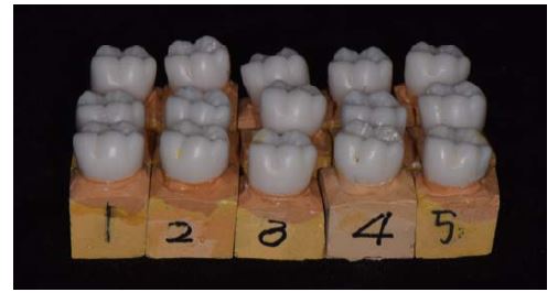
지르코니아관은 동일한 CAD/CAM milling machine(Ceramill motion 2, Amann Girrbach, Germany)을 이용하여 제작하였다. 모든 지르코니아관은 변연에서 1 mm 상방에 60 ㎛의 시멘트 공간을 부여하고 하악 제1대구치의 치관 형태로 디자인하였으며, 지르코니아 블록(Zolid, Amann Girrbach, Germany)을 사용하여 밀링하였다. 밀링 후 소성로(Ceramilll therm, Amann Girrbach, Germany)에서 20℃에서 1450℃까지 온도를 상승시킨 후 1450℃에서 2시간 동안 온도를 유지하며 소성하여 완성하였다(Figure 2, 3).
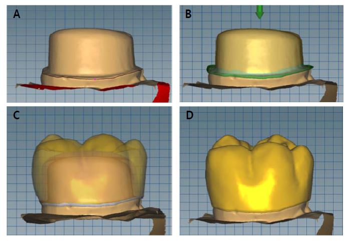
Zirconia crown design process (A. marginal line verification, B. 60 ㎛ of virtual cement spacer starting at 1 mm above the margin, C. crown design, D. completed design of zirconia crowns).
3. 변연 간극 및 내면 간극 측정
변연 간극과 내면 간극을 측정하기 위해 실리콘 레플리카 술식을 이용하였다. 지르코니아관 내부를 저점도 실리콘 인상재(Examixfine injection type, GC America Inc., USA)로 채우고 지대치에 위치시켰다. 균일한 압력을 가하기 위하여 만능재료시험기(Instron 3345; Instron, Canton, MA, USA)를 이용해 50 N의 일정한 힘을 주고 5분간 유지시킨 후, 지르코니아관을 분리하였다. 레플리카 외측에 중간 점도의 실리콘 인상재(Examixfine regular type, GC America Inc, USA)로 박싱을 시행하여 축벽을 쌓아올렸다. 내면에서의 실리콘 두께를 측정하기 위해 중앙에서 협설면과 근원심면으로 수술용 칼(Kiato plus, Adityadispomed, India)을 이용하여 4등분 하였다(Figure 4).
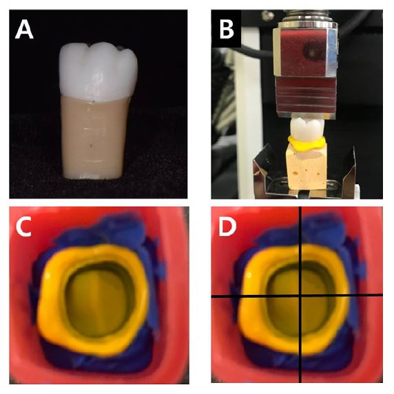
Measurement with silicone replica technique. A. zirconia crown fabricated on each die, B. silicone material was applied on the inner surface of crown and crown was loaded on the corresponding die with a vertical force of 50 N, C. silicone replica, D. silicone replica was sectioned into four pieces using a sharp scalpel blade.
4등분한 실리콘 인상재에서 총 16개의 측정위치를 정하고 각각의 지점에서 디지털 현미경(JTZ-7XT, Samwon, Korea)으로 160배의 배율하에서 실리콘 레플리카의 두께를 수직으로 측정하였다(Figure 5). 16개의 측정 지점은 (1) marginal discrepancy (MG) – 1, 8, 9, 16 point, (2) cervical discrepancy (CG) – 2, 7, 10, 15 point, (3) axial discrepancy (AG) – 3, 6, 11, 14 point, (4) occlusal discrepancy (OG) – 4, 5, 12, 13 point로 나누었다(Figure 6).
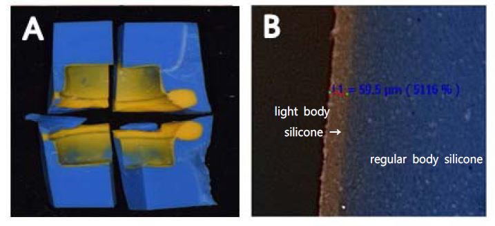
Measurement of discrepancy (A. sectioned silicone replica, B. replica sections were observed with a stereomicroscope at ×160 magnification).
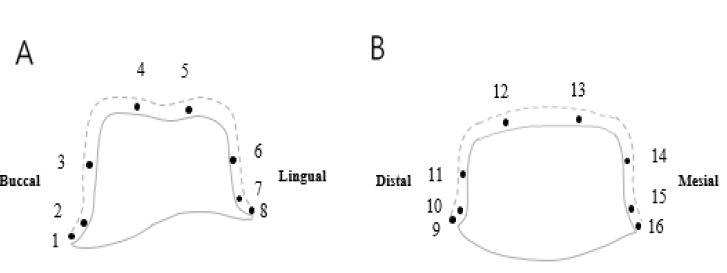
Reference points to measure the thickness. Measurement areas are designated according to the replica technique (A. Buccolingual section; 1,8-marginal discrepancy (MG), 2,7-cervical discrepancy (CG), 3,6-axial discrepancy (AG), 4,5-occlusal discrepancy (OG), B. Mesiodistal section; 9,16-marginal discrepancy (MG), 10,15-cervical discrepancy (CG), 11,14-axial discrepancy (AG), 12,13-occlusal discrepancy (OG)).
4. 통계 분석
SPSS software program (SPSS 20.0, SPSS Inc., USA)을 이용하여 각군 보철물의 변연 간극과 내면 간극(치경부, 축면, 교합면)을 측정한 결과값을 one-way ANOVA로 통계처리하고, Duncan's multiple range test (α=0.05)로 사후검정을 시행하였다.
결 과
1. 변연 간극(MG - 1, 8, 9, 16) (Table 2)
각 군마다 실체 현미경으로 15개 인상재에서의 측정 지점을 각각 측정하여 평균값을 비교한 결과, OS군(56.5±55.9 ㎛)과 MS군 (78.6±64.7 ㎛)이 낮은 간격을 보여 IS군(119.1±85.2 ㎛), CT군 (180.1±149.5 ㎛)과 유의한 차이를 보였고(p<0.05), OS군과 MS군 간에 유의한 차이는 없었다(p>0.05).
2. 내면 간극(Table 3)
치경부 간극의 평균값을 비교한 결과, OS군 (127.6±108.3 ㎛)이 가장 낮게 나타났으며 이는 다른 군들보다 유의성 있게 작았다(p<0.05). MS군(239.3±55.5 ㎛)은 IS군(202.4±213.5 ㎛), CT군(260.1±143.9 ㎛)과 통계적으로 유의한 차이가 나타나지 않았다(p>0.05).
축면부 간격의 평균값을 비교한 결과, IS군(45.3±20.9㎛)이 가장 낮게 나타났고, MS군(73.4±23.8 ㎛)이 가장 크게 나타나 통계적으로 유의한 차이가 있었다 (p<0.05). OS군(60.9±17.8 ㎛)과 CT군(59.9±20.9 ㎛)은 서로 유의한 차이를 보이지 않았다(p>0.05).
교합면 간격의 평균값을 비교한 결과, OS군(135.4±51.7 ㎛)이 가장 낮게 나타났고, CT (311.2±172.0 ㎛)이 가장 크게 나타나 유의한 차이가 있었다 (p<0.05). MS군(155.1±41.7 ㎛)은 OS군 (135.4±51.7 ㎛), IS군(184.9±79.8 ㎛)과 통계적으로 유의한 차이를 나타내지 않았다(p>0.05).
고 찰
디지털 치의학과 CAD/CAM 기술의 지속적 발달은 보철물 제작의 임상 과정과 기공 과정에 큰 변화를 가져왔다. 3차원 모형은 컴퓨터상에서 진단과 분석, 그리고 데이터 보관이 이루어지므로 석고 모형과 달리 훼손이나 분실, 보관공간의 문제가 없어 매우 유용하다(15). 또한 최근에는 진료실에 치과용 CT 보급이 증가하여 치과용 고해상도의 CT를 이용하여 디지털 모형을 제작할 수 있는 환경이 되었으며, 디지털 계측 및 분석 과정이 단순히 진단에 머무르지 않고 컴퓨터상에서 바로 교정 구외 장치나 수술 장치를 디자인하고, 바로 제작하는 과정까지 연계되고 있다(15-17).
보철물의 정확성을 평가함에 있어 보철물의 적합도는 중요한 요소 중 하나이다. 올세라믹관의 적절하지 않은 변연 적합도는 시멘트 용해, 치은염, 이차 치아 우식증을 야기시킬 수 있고, 적절하지 않은 내면 적합도의 경우, 올세라믹관의 파절 강도에 영향을 미칠 수 있다(18). Holmes 등은 보철물의 적합도를 측정하는 기준으로서 지대치의 축면에서 수복물의 내면까지 수직거리를 내면 간극이라하고 특별히 변연부에서는 변연 간극이라고 제시하였다(19). 임상적으로 수용 가능한 변연 간극에 대해서는 현재까지 많은 논란이 있는데, McLean 등은 변연간극이 100~120 ㎛에서 임상적으로 허용 가능한 상태라고 보고하였으며(20), Hung 등은 금속 도재관(porcelain fused metal crown)과 올세라믹관에서 허용 가능한 변연 간극을 50~75 ㎛라고 하였다(21). Weaver 등은 적절한 변연 간극을 70±10 ㎛로 보고하였으며(22), Rinke 등은 올세라믹관은 18~145 ㎛의 변연 간극을 보여준다고 하였다(23). Euan 등은 CAD/CAM으로 제작된 보철물에 있어서 최소한의 수용할 만한 변연 간극은 100㎛이하라고 하였으며(24), Beuer 등의 연구에서는 Belser등의 보고를 종합하여 CAD/CAM으로 제작된 보철물의 경우 변연 간극이 120 ㎛이하인 경우 임상적으로 사용 가능하다는 보다 유연한 기준을 제시하였다(25, 26). 내면 간극 또한 수복물의 성공을 결정짓는 중요한 요소이다. 내면 간극이 커지면 지대치와 수복물 사이의 기계적 유지력이 감소하게 되고, 수복물의 탈락은 증가하게 되며(27), 상대적으로 낮은 탄성계수를 지닌 치과용 시멘트가 두꺼워지면서 강도가 감소하게 된다(28, 29). 따라서 올세라믹관과 같이 취성이 강한 재료로 만든 수복물은 내면 간극이 더욱 중요하다. Molin 등 여러 연구들에서 올세라믹관의 가장 이상적인 내면 간극은 50~100 ㎛으로 보고되었고(30), 100 ㎛ 이상의 시멘트 공간은 시멘트와 도재의 파절을 증가시키나(31), 200~300 ㎛의 내면 간극도 임상적으로는 허용 가능한 상태라고 하였다(32, 33). 지르코니아관의 시멘트 공간은 CAD/CAM 장비의 소프트웨어를 이용하여 설정하는데, 이 과정에서의 설정값에 따라 변연 간극과 내면 간극이 달라졌다는 연구들이 있다. Iwai 등의 연구에서는 60 ㎛의 시멘트 공간을 부여하였을 때 CAD/CAM을 이용하여 제작한 보철물의 변연 간극과 내면 간극이 가장 좋았다고 하였으며(34), Mously 등의 연구에서는 30~60 ㎛의 공간이 추천된다고 하였다(35). 이에 본 연구에서는 여러 연구 결과를 따라 지르코니아관 내면에 60 ㎛의 공간을 부여하였다.
올세라믹관의 변연 간극과 내면 간극을 측정하는 방법은 표준화되어 있는 기준이 없다. 많은 연구에서 보철물의 간극을 평가하기 위하여 각각 다른 측정 방식이 사용되었고, 이러한 점이 결과에 어떠한 영향을 미쳤는지에 대한 연구는 부족하다. 가장 흔하게 사용되는 방법으로는 측정하고자하는 지점에서 현미경으로 직접 관찰하는 방법과 시편을 절단하여 내면의 간극을 측정하는 방법(36), 인상재를 이용한 실리콘 레플리카 술식이 내면 간극을 평가하기 위하여 많이 사용되고 있다. 본 연구에서는 실리콘 레플리카 술식으로 지르코니아관의 변연 간극 및 내면 간극을 비교평가 하였다. 실리콘 레플리카 술식(silicone replica technique)은 Molin과 Karlsson등이 1993년 gold inlay와 ceramic inlay의 적합도 비교를 위한 연구에서 사용한 실험방법이다(37). 이 방법은 수복물을 절단할 필요가 없기 때문에 간단하고, 측정하고자 하는 위치나 재료의 종류의 영향을 받지 않으며, 시편을 재활용 할 수 있다는 장점이 있다. 그러나, 저점도 실리콘이 찢어지거나 변형될 가능성이 있으며, 마찬가지로 2차원적인 단면 측정만 가능하다(38, 39). 과거에는 이 방법의 정확도에 대해서 의문점이 제기되기도 하였는데, 이에 Habib 등은 동일한 시편을 이용하여 내면 적합도를 비교측정 해봄으로써, 수복물을 절단해서 관찰하는 전통적인 방법과 실리콘 레플리카 술식 사이의 정밀도를 비교 평가하였는데, 정밀도에서 두 방법 사이에 유의한 차이가 없다고 보고하였다(39).
본 연구에서 지르코니아관의 변연 간극을 측정하여 평균값을 비교한 결과, 모형 스캔이 78.6±64.7 ㎛, 구내 스캔이 56.5±55.9 ㎛로 낮은 간격을 보였으며, 119.1±85.12 ㎛의 인상체 스캔과 180.1±149.5 ㎛의 CT 스캔과 유의한 차이를 보였다. 모형 스캔, 인상체 스캔, 구내 스캔 세 가지 군에서는 McLean이 언급한 임상적으로 허용 가능하다고 통상적으로 판단하는 120 ㎛ 범위 안의 변연 간극을 보였으나, CT 스캔군은 임상적으로 사용하기에 부적절한 변연 간극을 보였다. Boeddinghaus 등의 연구에서 구강 스캐너와 모델 스캐너의 변연 간극은 차이가 없다고 하였으며(27), 몇몇 다른 연구에서는 구강 스캐너가 모델 스캐너보다 우수한 변연 간극을 보인다고 하였는데(40, 41), 본 연구의 결과에서도 구강 스캐너가 모델 스캐너보다 우수한 변연 간극을 보임을 확인할 수 있었다.
내면 간극은 치경부 간극의 평균값을 비교한 결과, 구내스캔이 127.6±108.3 ㎛로 가장 낮게 나타나 다른 군과 통계적으로 유의한 차이가 있었고, CT 스캔(260.1±143.9㎛)과 모형 스캔(239.3±55.5 ㎛)은 서로 유의한 차이가 나타나지 않았다. 축면부 간극의 평균값은 인상체 스캔이 45.3±20.9 ㎛로 가장 낮게 나타났고, 모형 스캔이 73.4±23.8 ㎛로 가장 크게 나타나 통계적으로 유의한 차이가 있었다. 교합면 간극의 평균값은 구내 스캔이 135.4±51.7㎛로 가장 낮게 나타났고, CT 스캔은 311.2±172.0 ㎛로 가장 크게 나타나 유의한 차이가 있었다. 본 연구에서는 전반적으로 변연 간극보다 내면 간극이 큰 결과값을 보였고, CT군을 제외한 모든 실험군에서 임상적으로 허용할 만한 범위 내의 간극을 보여주었다.
최근 3차원 분석과 진단을 위해 구강 악안면 영역에서 치과용 CT의 활용이 증가하고 있으며, 해상도 또한 0.07~0.1mm 정도까지 정밀해지고 있다. 치과용 CT는 voxel size가 작을수록 변환된 디지털 모형의 표면정확도가 개선되는데, 본 연구에서는 0.1 mm의 해상도로 주모형을 스캔함으로써 디지털 모형의 정확도를 보다 높이고자 하였다. 연구에 사용된 모델 스캐너의 해상도는 10 ㎛로 CT 스캔보다 모형의 표면이 보다 균일하며 이는 전체적으로 보다 나은 결과값 도출의 원인이 되었으리라 사료된다. 또한 CT 데이터를 통한 3차원 이미지 구성 시 교두와 소와 열구 부위는 모형 표면의 거친 질감을 유발하기 때문에 모형을 구성할 때 교두와 소와 열구 부위의 값이 일부 평탄화된다(42). 이로 인해 교두와 소와 열구 부위의 오차가 발생하게 되는데, 본 연구 결과에서 보여준 CT 스캔의 교합면 간극이 축면간극에 비해 큰 것도 이러한 원인으로 생각해 볼 수 있다. 이 밖에도 치과용 CT 촬영 시 산란 방사선으로 인한 노이즈의 증가, 빔경화 효과나 영상처리 과정에서 발생되는 인공음영 등이 영상의 질을 저하시킬 수 있다(43). Kwon 등은 치과용 CT 영상으로부터 구성된 디지털 모형의 오차는 약 70 ㎛보다 크며(44), 평균값은 120 ㎛보다는 작다고 하였다. Beuer 등은 광학 스캔을 이용한 CAM 보철물이 가지게 되는 변연간극의 평균값이 CAD/CAM 시스템의 종류에 따라 최소의 경우 9 ㎛에서 최대 108 ㎛의 값을 가진다고 보고하였다(25). 따라서 치과용 CT를 이용해 제작된 디지털 모형에서 제작된 보철물은 이러한 오차가 중첩되어 나타나게 된다. 이 외에, DICOM (digital imaging communication in medicine)파일을 STL 파일로 변환하는 과정에서 발생할 수 있는 소프트웨어상의 오차도 고려되어져야 할 것이다.
CAD/CAM 시스템을 이용하는 보철물은 스캔 과정, 소프트웨어에서 디자인하는 과정, 절삭가공 과정, 소결 후 수축하는 과정 중에 오차가 발생할 수 있다(45). 반소결 지르코니아 블록은 소결 과정에서 15~30%의 수축하게 되는데 이 과정에서도 오차가 발생된다(46). Kohorst 등은 서로 다른 CAD/CAM 시스템과 재료를 대상으로 한 연구에서 변연 오차를 보고하는데, 완전소결 지르코니아 블록군의 경우 평균 52.7㎛이었지만, 반소결 지르코니아 블록을 사용한 나머지 군의 변연 오차는 185.4~190.4 ㎛의 범위였고, 그 중 한 군의 최대값은 308.5 ㎛에 달하였다(47). 본 연구에서도 반소결 지르코니아 블록을 사용하였으며, 간극 크기가 기존 연구들 보다 다소 큰 경향을 보였다.
본 연구는 환자 구강 내 조건과 치과적 특성들에 대한 영향이 배제된 실험실 내 연구이다. 본 연구의 한계 내에서 모형 스캔, 인상체 스캔과 구내 스캔을 통해 제작된 보철물이 임상적으로 사용되기에 큰 무리가 없음을 확인하였다. 다만, 치과용 CT 스캔을 이용한 디지털 모형을 최종 보철물 제작에 사용하기 위해서는 자주 발생하는 3차원 영상 구성상의 오류를 파악하여 그에 맞는 영상처리 기법을 적용하는 것이 필요할 것이며, 치과용 CT의 해상도 개선과 DICOM 파일의 STL 파일로의 변환 소프트웨어의 개발이 더 필요할 것으로 사료된다
결 론
모형 스캔, 인상체 스캔과 구내 스캔을 통해 제작된 보철물의 변연 간극과 내면 간극은 임상적으로 허용할 만한 범위 내에 있어 임상적으로 사용되기에 큰 무리가 없으나, 치과용 CT 스캔은 현재까지 적합도 면에서 보철물 제작에 사용하기 어렵다.
References
-
Krishna J, Kumar S, Savadi RV. Evalution of metal free ceramics. J Indian Prosthodont Soc 2009;9:70-5.
[https://doi.org/10.4103/0972-4052.55247]

-
Gehrt M, Wolfart S, Rafai N, Reich S, Edelhoff D. Clinical results of lithium- disilicate crowns after up to 9 years of service. Clinical Oral Investig 2012;17:275-84.
[https://doi.org/10.1007/s00784-012-0700-x]

-
Seghi RR, Daher T, Caputo A. Relative flexural strength of dental restorative ceramics. Dent Mater 199;6:181-4.
[https://doi.org/10.1016/0109-5641(90)90026-B]

-
Delong R, Pintado MR, Ko CC, Hodges JS, Douglas WH. Factors influencing optical 3D scanning of vinyl polysiloxane impression materials. J Prosthodont 2001;10:78-85.
[https://doi.org/10.1111/j.1532-849X.2001.00078.x]

-
Delong R, Pintado M, Douglas WH. Measurement of change in surface contour by computer graphics. Dent Mater 1985;1:27-30.
[https://doi.org/10.1016/S0109-5641(85)80061-0]

-
Flugge TV, Schlager S, Nelson K, Nahles S, Metzger MC. Precision of intraoral digital dental impressions with iTero and extraoral digitization with the iTero and a model scanner. Am J Orthod Dentofacial Orthop 2013;144:471-8.
[https://doi.org/10.1016/j.ajodo.2013.04.017]

-
Kato A, Ohno N. Construction of three-dimensional tooth model by micro-computed tomography and application for data sharing, Clin Oral Investig 2009;13:43-6.
[https://doi.org/10.1007/s00784-008-0198-4]

-
Lim MY, Lim SH. Comparison of model analysis measurements among plaster model, laser scan digital model, and cone beam CT image. Korean J Orthod 2009;39:6-17.
[https://doi.org/10.4041/kjod.2009.39.1.6]

-
Swennen GR, Mommaerts MY, Abeloos J, De Clercq C, Lamoral P, Neyt N, Schutyser FA. A cone-beam CT based technique to augment the 3D virtual skull model with a detailed dental surface. Int J Oral Maillofac Surg 2009;38:48-57.
[https://doi.org/10.1016/j.ijom.2008.11.006]

-
Reuschl RP, Heuer W, Stiesch M, Wenzel D, Dittmer MP: Reliability and validity of measurements on digital study models and plaster models. Eur J Orthod, 2016:38:22-6.
[https://doi.org/10.1093/ejo/cjv001]

-
Zhao S, Robertson DD, Wang G, Whiting B, Bae KT. X-ray CT metal artifact reduction using wavelets: an application for imaging total hip prostheses. IEEE Trans Med Imaging 2000;19:1238-47.
[https://doi.org/10.1109/42.897816]

-
Della Bona A, Kelly JR. The clinical success of all-ceramic restorations. J Am Dent Assoc 2008:139:8S-13S.
[https://doi.org/10.14219/jada.archive.2008.0361]

-
Chan C, Weber H. Plaque retention on teeth restored with full-ceramic crowns: A comparative study. J Prosthet Dent 1986;55:666-71.
[https://doi.org/10.1016/0022-3913(86)90140-X]

-
Bergenholtz G, Cox CF, Loesche WJ, Syed SA. Bacterial leakage around dental restorations: its effect on the dental pulp. J Oral Pathol 1982;11:439–50.
[https://doi.org/10.1111/j.1600-0714.1982.tb00188.x]

- Zilberman O1, Huggare JA, Parikakis KA. Evaluation of the validity of tooth size and arch width measurements using conventional and three-dimensional virtual orthodontic models. Angle Orthod 2003;73:301-6.
-
Bootvong K, Liu Z, McGrath C, Hägg U, Wong RW, Bendeus M, Yeung S. Virtual model analysis as an alternative approach to plaster model analysis: reliability and validity. Eur J Orthod 2010;32:589-95.
[https://doi.org/10.1093/ejo/cjp159]

-
Keating AP, Knox J, Bibb R, Zhurov AI. A comparison of plaster, digital and reconstructed study model accuracy. J Orthod 2008;35:191-201.
[https://doi.org/10.1179/146531207225022626]

- Moon BH, Yang JH, Lee SH, Chung HY. A study on the marginal fit of all-ceramic crown using CCD camera. J Korean Acad Prosthodont 1998;36:273-92.
-
Holmes JR, Bayne SC, Holland GA, Sulik WD. Considerations in measurement of marginal fit. J Prosthet Dent. 1989;62:405-8.
[https://doi.org/10.1016/0022-3913(89)90170-4]

-
McLean JW, von Fraunhofer JA. The estimation of cement film thickness by an in vivo technique. Br Dent J 1971;131:107-11.
[https://doi.org/10.1038/sj.bdj.4802708]

-
Hung SH, Hung KS, Erik JD, Chappell RP. Marginal fit of porcelain-fused-to-metal and two types of ceramic crown. J Prosthet Dent 1990;63:26-31.
[https://doi.org/10.1016/0022-3913(90)90260-J]

-
Weaver JD, Johnson GH, Bales DJ. Marginal adaptation of castable ceramic crowns. J Prosthet Dent 1991;66:747-53.
[https://doi.org/10.1016/0022-3913(91)90408-O]

- Rinke S, Hüls A, Jahn L. Marginal accuracy and fracture strength of conventional and copy-milled all-ceramic crowns. Int J Prosthodont 1995;8:303–10.
-
Euan R, Figueras-Alvarez O, Cabratosa-Termes J, Oliver-Parra R. Marginal adaptation of zirconium dioxide copings: Influence of the CAD/CAM system and the finish line design. J Prosthet Dent 2014;112:155-62.
[https://doi.org/10.1016/j.prosdent.2013.10.012]

-
Beuer F, Naumann M, Gernet W, Sorensen JA. Precision of fit: zirconia three-unit fixed dental prostheses. Clin Oral Investig 2009;13:343-9.
[https://doi.org/10.1007/s00784-008-0224-6]

-
Belser UC, MacEntee MI, Richter WA. Fit of three porcelain-fused-to-metal marginal designs in vivo: a scanning electron microscope study. J Prosthet Dent 1985;53:24-9.
[https://doi.org/10.1016/0022-3913(85)90058-7]

-
Boeddinghaus M, Breloer ES, Rehmann P, Wöstmann B. Accuracy of single tooth restorations based on intraoral digital and conventional impressions in patients. Clin Oral Investig 2015;19:2027-34.
[https://doi.org/10.1007/s00784-015-1430-7]

-
May LG, Kelly JR, Bottino MA, Hill T. Effects of cement thickness and bonding on the failure loads of CAD/CAM ceramic crowns. Dent Mater 2012;28:99- 109.
[https://doi.org/10.1016/j.dental.2012.04.033]

-
Kokubo Y, Ohkubo C, Tsumita M, Miyashita A, Vult von Steyern P, Fukushima S. Clinical marginal and internal gaps of Procera All Ceram crowns. J Oral Rehabil 2005;32:526-30.
[https://doi.org/10.1111/j.1365-2842.2005.01458.x]

-
Molin MK, Karlsson SL, Kristiansen MS. Influence of film thickness on joint bend strength of a ceramic/resin composite joint. Dent Mater1996;12:245-9.
[https://doi.org/10.1016/S0109-5641(96)80030-3]

-
Molin M, Karlsson S. The fit of gold inlays and three ceramic inlay systems: A clinical and in vitro study. Acta Odontol Scand 1993;51:201-6.
[https://doi.org/10.3109/00016359309040568]

- Mörmann WH, Bindl A, Lüthy H, Rathke A. Effects of preparation and luting system on all-ceramic computer-generated crowns. Int J Prosthodont 1998;11:333-9.
-
Sorensen JA, Munksgaard EC. Interfacial gaps of resin cemented ceramic inlays. Eur J Oral Sci 1995;103:116-20.
[https://doi.org/10.1111/j.1600-0722.1995.tb00128.x]

-
Iwai T, Komine F, Kobayashi K, Saito A, Matsumura H. Influence of convergence angle and cement space on adaptation of zirconium dioxide ceramic copings. Acta Odontol Scand 2008;66:214-8.
[https://doi.org/10.1080/00016350802139833]

-
Mously HA, Zandparsa R, Hirayama H. Marginal and internal adaptation of ceramic crown restorations fabricated with CAD/CAM technology and the heat-press technique. J Prosthet Dent 2014;112:249–56.
[https://doi.org/10.1016/j.prosdent.2014.03.017]

-
Weyns W, De Boever J. Radiographic assessment of the marginal fit of cast restorations. J Prosther Dent 1984;51:485-9.
[https://doi.org/10.1016/0022-3913(84)90298-1]

-
Molin M, Karlsson S. The fit of gold inlays and three ceramic inlay systems: A clinical and in vitro study. Acta Odontol Scand 1993;51:201-6.
[https://doi.org/10.3109/00016359309040568]

-
Laurent M, Scheer P, Dejou J, Laborde G. Clinical evaluation of the marginal fit of cast crowns: validation of the silicone replica method. J Oral Rehabil 2008;35:116-22.
[https://doi.org/10.1111/j.1365-2842.2003.01203.x]

- Rahme HY, Tehini GE, Adib SM, Ardo AS, Rifai KT. In vitro evaluation of the "replica technique" in the measurement of the fit of Procera crowns. J Contemp Dent Pract 2008;9:25-32.
-
Syrek A, Reich G, Ranftl D, Klein C, Cerny B, Brodesser J. Clinical evaluation of all-ceramic crowns fabricated from intraoral digital impressions based on the principle of active wavefront sampling. J Dent 2010;38:553-9.
[https://doi.org/10.1016/j.jdent.2010.03.015]

-
Flügge TV, Schlager S, Nelson K, Nahles S, Metzger MC. Precision of intraoral digital dental impressions with iTero and extraoral digitization with the iTero and a model scanner. Am J Orthod Dentofacial Orthop 2013 ;144:471-8.
[https://doi.org/10.1016/j.ajodo.2013.04.017]

-
Lautenschlager EP, Harcourt JK, Ploszaj LC. Setting reactions of gypsum materials investigated by X-ray diffraction. J Dent Res 1969;48:43-8.
[https://doi.org/10.1177/00220345690480012301]

-
Chee WW, Donovan TE. Polyvinyl siloxane impression materials: a review of properties and techniques. J Prosthet Dent 1992;68:728-32.
[https://doi.org/10.1016/0022-3913(92)90192-D]

-
Hyuk-Jin Kwon, Kack-Kyun Kim, Won-Jin Yi. Comparison of digital models generated from three-dimensional optical scanner and cone beam computed tomography. J Dent Rehabil Appl Sci 2016;32:60-9.
[https://doi.org/10.14368/jdras.2016.32.1.60]

-
Reich S, Wichmann M, Nkenke E, Proeschel P. Clinical fit of all-ceramic three-unit fixed partial dentures, generated with three different CAD/CAM systems. Eur J Oral Sci 2005;113:174-9.
[https://doi.org/10.1111/j.1600-0722.2004.00197.x]

- Suttor D, Bunke K, Hoescheler S, Hauptmann H, Hertlein G. LAVA – the system for all-ceramic ZrO2 crown and bridge frameworks. Int J Comput Dent 2001;4:195-206.
-
Kohorst P, Brinkmann H, Li J, Borchers L, Stiesch M. Marginal accuracy of four-unit zirconia fixed dental prostheses fabricated using different computer-aided design/computer-aided manufacturing systems. Eur J Oral Sci 2009;117:319-25.
[https://doi.org/10.1111/j.1600-0722.2009.00622.x]


